CNC Machine
Preventing Motor VFD Interference with Chassis Grounding
A VFD switches fast, and that switching puts electrical noise into everything around it, including you. Here is how to ground a 2×72 chassis, motor and drive properly, route the cables, and stop the interference and nuisance trips.

A VFD makes variable speed possible by switching the motor supply thousands of times a second, and all that switching puts electrical noise into everything around it, including the grinder frame you have your hands on. Grounding is how you tame it. Here is how I ground a 2×72 chassis, motor and drive, how I route the cables, and how to stop the interference and nuisance trips that come with a bad ground.
These spikes can propagate through power lines and radiate into the surrounding environment, causing disruptions in sensitive electronic devices. Understanding this phenomenon is crucial for engineers and technicians who design and maintain systems that incorporate VFDs. The interference generated by VFDs can manifest in various ways, including erratic behavior of control systems, unexpected shutdowns, and even damage to sensitive components.
Key Takeaways
- Motor VFD interference can negatively impact equipment and systems, leading to malfunctions and downtime.
- Chassis grounding is crucial in VFD systems to prevent interference and ensure proper functioning of equipment.
- Common sources of VFD interference include electromagnetic radiation and conducted emissions.
- VFD interference can cause equipment malfunctions, data errors, and communication disruptions.
- Prevent VFD interference with proper chassis grounding, shielded cables, and regular maintenance.
Importance of Chassis Grounding in VFD Systems
Chassis grounding plays a pivotal role in minimizing the effects of VFD interference. A well-designed grounding system provides a low-resistance path for stray currents and helps to dissipate electromagnetic noise. This is particularly important in environments where multiple VFDs operate in close proximity, as the cumulative effect of their interference can lead to significant operational issues.
Proper chassis grounding not only enhances the performance of VFDs but also safeguards other equipment from potential damage caused by EMI. Effective grounding practices contribute to personnel safety by reducing the risk of electric shock. In industrial settings, where workers may be in close contact with machinery, a reliable grounding system ensures that any fault currents are safely directed away from operators.
Common Sources of VFD Interference
VFD interference can originate from several sources, each contributing to the overall electromagnetic noise in an industrial environment. One primary source is the rapid switching of the power transistors within the VFD itself. This switching action generates high-frequency voltage spikes that can propagate through power lines and radiate into nearby equipment.
The layout of electrical wiring can exacerbate these issues; for instance, long cable runs can act as antennas, picking up and transmitting noise. Another common source of interference is the interaction between multiple VFDs operating on the same power supply. When several drives are connected to a shared bus, their switching actions can create a cumulative effect that amplifies EMI levels.
External factors such as nearby radio frequency transmitters or other industrial equipment can introduce additional noise into the system. Understanding these sources is essential for developing effective mitigation strategies.
Impact of VFD Interference on Equipment and Systems
The impact of VFD interference on equipment and systems can be profound, leading to a range of operational challenges. One significant consequence is the potential for erratic behavior in control systems, which may result in inaccurate readings or unintended actions by machinery. This unpredictability can disrupt production processes and lead to costly downtime.
In severe cases, it may even cause physical damage to sensitive components, necessitating expensive repairs or replacements. Moreover, VFD interference can compromise the reliability of communication systems within an industrial setup. Many modern control systems rely on digital communication protocols that are susceptible to noise.
Strategies for Preventing VFD Interference with Chassis Grounding
To effectively prevent VFD interference, implementing sturdy chassis grounding strategies is essential. One key approach is to ensure that all equipment is properly grounded to a common reference point. This minimizes potential differences between various components and reduces the likelihood of stray currents causing interference.
Using low-resistance grounding conductors can enhance the effectiveness of the grounding system. Another strategy involves isolating sensitive equipment from VFDs through physical separation or shielding techniques. By placing critical control systems away from VFDs or using barriers that absorb or deflect EMI, engineers can significantly reduce the impact of interference.
Proper Installation of Grounding Systems
The installation of grounding systems is a critical step in mitigating VFD interference. Proper installation begins with selecting appropriate grounding materials and methods that comply with industry standards and regulations. Grounding electrodes should be installed at strategic locations to provide optimal conductivity and minimize resistance.
Connections should be made securely to prevent loosening over time, which could compromise the effectiveness of the grounding system. It is essential to consider the layout of grounding conductors during installation. Conductors should be routed in a manner that minimizes inductance and resistance while avoiding sharp bends or loops that could introduce additional noise.
Utilizing Shielded Cables and Wiring
In addition to proper grounding practices, utilizing shielded cables and wiring is an effective strategy for reducing VFD interference. Shielded cables are designed with conductive layers that encase the inner conductors, providing a barrier against electromagnetic noise. This shielding helps to prevent external interference from affecting signal integrity while also containing any noise generated by the VFD itself.
When selecting shielded cables, it is important to choose those with appropriate shielding effectiveness for the specific application. The type of shielding—whether foil or braided—can influence performance based on factors such as frequency range and environmental conditions. By incorporating shielded cables into their designs, engineers can significantly enhance the resilience of their systems against VFD-related EMI.
Implementing Proper Cable Routing and Separation
Proper cable routing and separation are critical components in minimizing VFD interference within an industrial environment. Cables should be routed away from sources of electromagnetic noise whenever possible, maintaining adequate distance between power cables associated with VFDs and sensitive signal cables. This separation helps to reduce inductive coupling, which can introduce unwanted noise into control signals.
Implementing organized cable management practices can further enhance system performance. Using cable trays or conduits not only keeps cables organized but also provides physical barriers that help shield sensitive wiring from EMI sources. By prioritizing thoughtful cable routing and separation strategies, engineers can create a more sturdy system less susceptible to interference.
Importance of Regular Maintenance and Inspection
Regular maintenance and inspection of grounding systems and associated wiring are vital for ensuring long-term effectiveness in mitigating VFD interference. Over time, environmental factors such as moisture, corrosion, or mechanical wear can compromise grounding connections or damage cables. Routine inspections allow technicians to identify potential issues before they escalate into significant problems that could disrupt operations.
During maintenance checks, it is essential to verify that all grounding connections remain secure and free from corrosion or other forms of degradation. Inspecting shielded cables for signs of wear or damage ensures that they continue to provide adequate protection against EMI. By establishing a proactive maintenance schedule, organizations can enhance system reliability and minimize the risk of VFD-related disruptions.
FAQs
What is chassis grounding?
Chassis grounding is the practice of connecting the metal frame or chassis of electrical equipment to the earth or a grounding system to provide a path for electrical currents to safely dissipate.
What are some common methods for implementing chassis grounding?
Common methods for implementing chassis grounding include connecting the chassis to a grounding electrode system, using grounding conductors, and ensuring proper bonding and grounding connections throughout the electrical system.
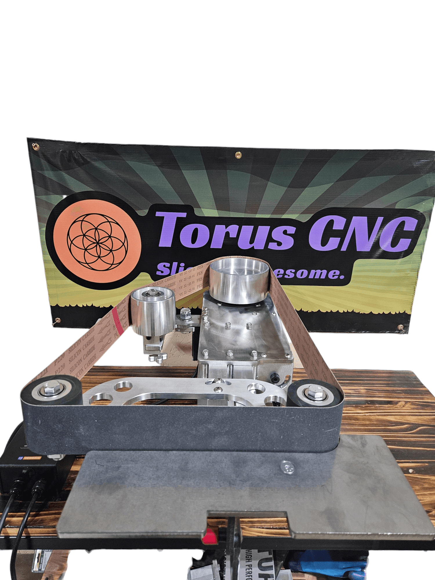
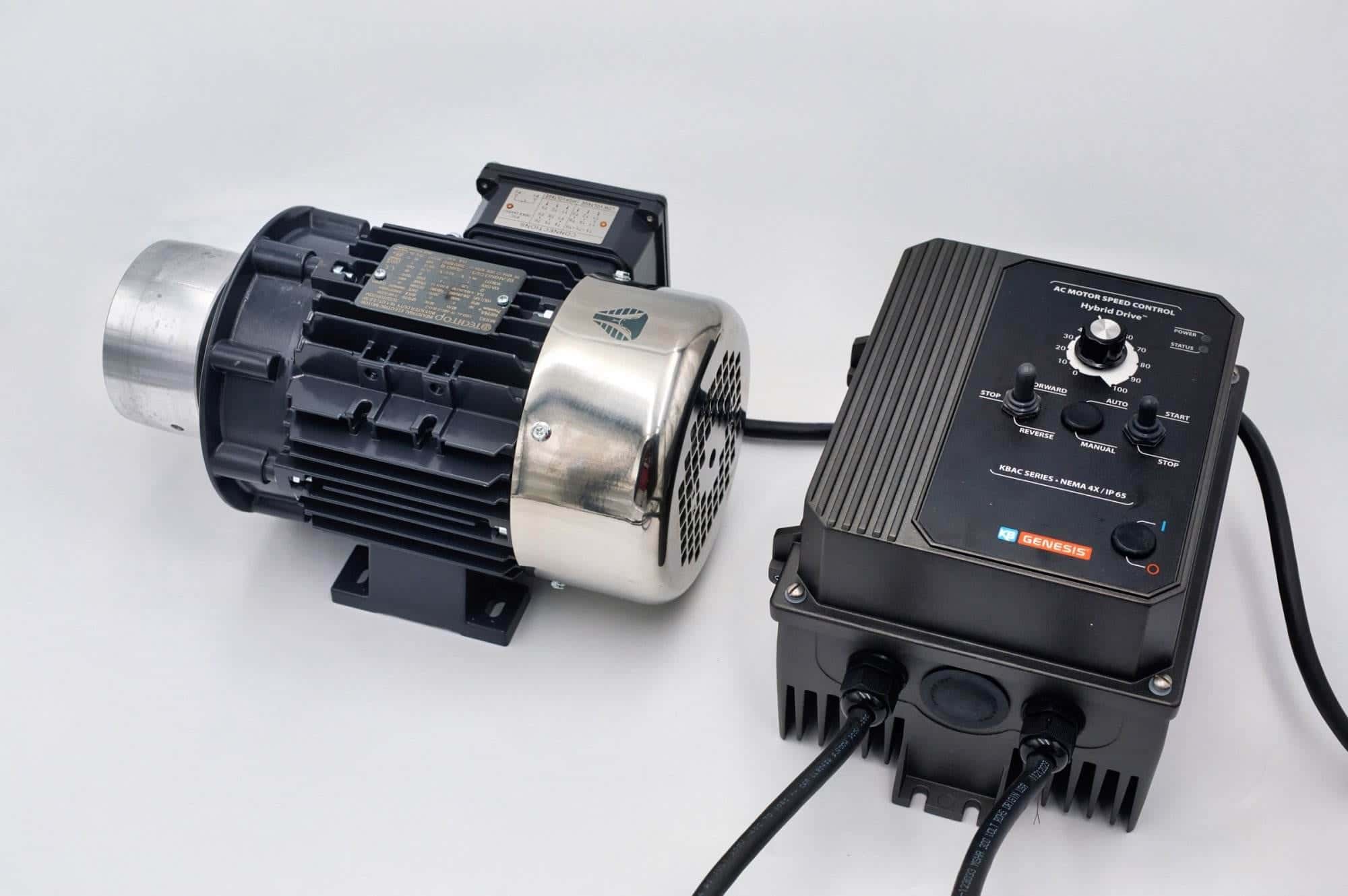
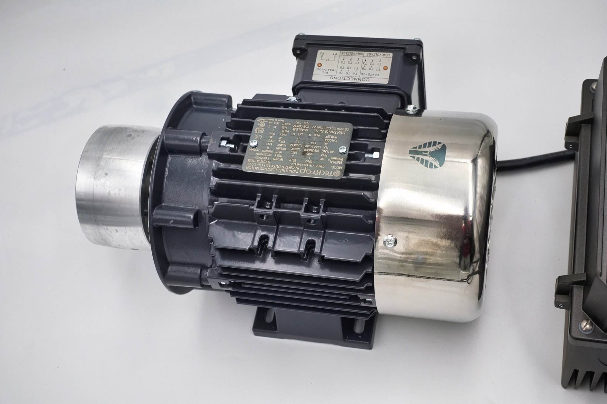
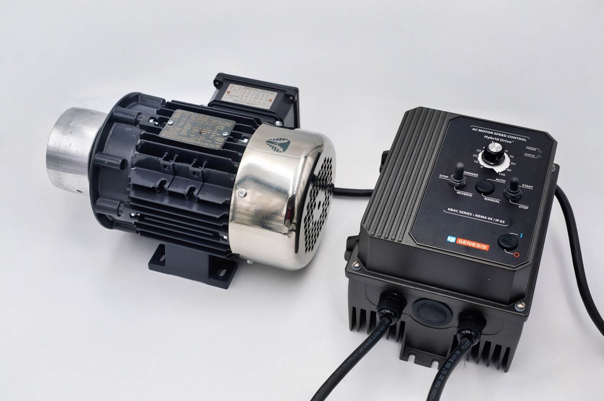
My motor and VFD combo comes wired and programmed on a grounded, sealed KBAC-27D drive, which takes most of the guesswork out. Mount it on a Nova 2×72 and follow my wiring guide for the cable and plug side.