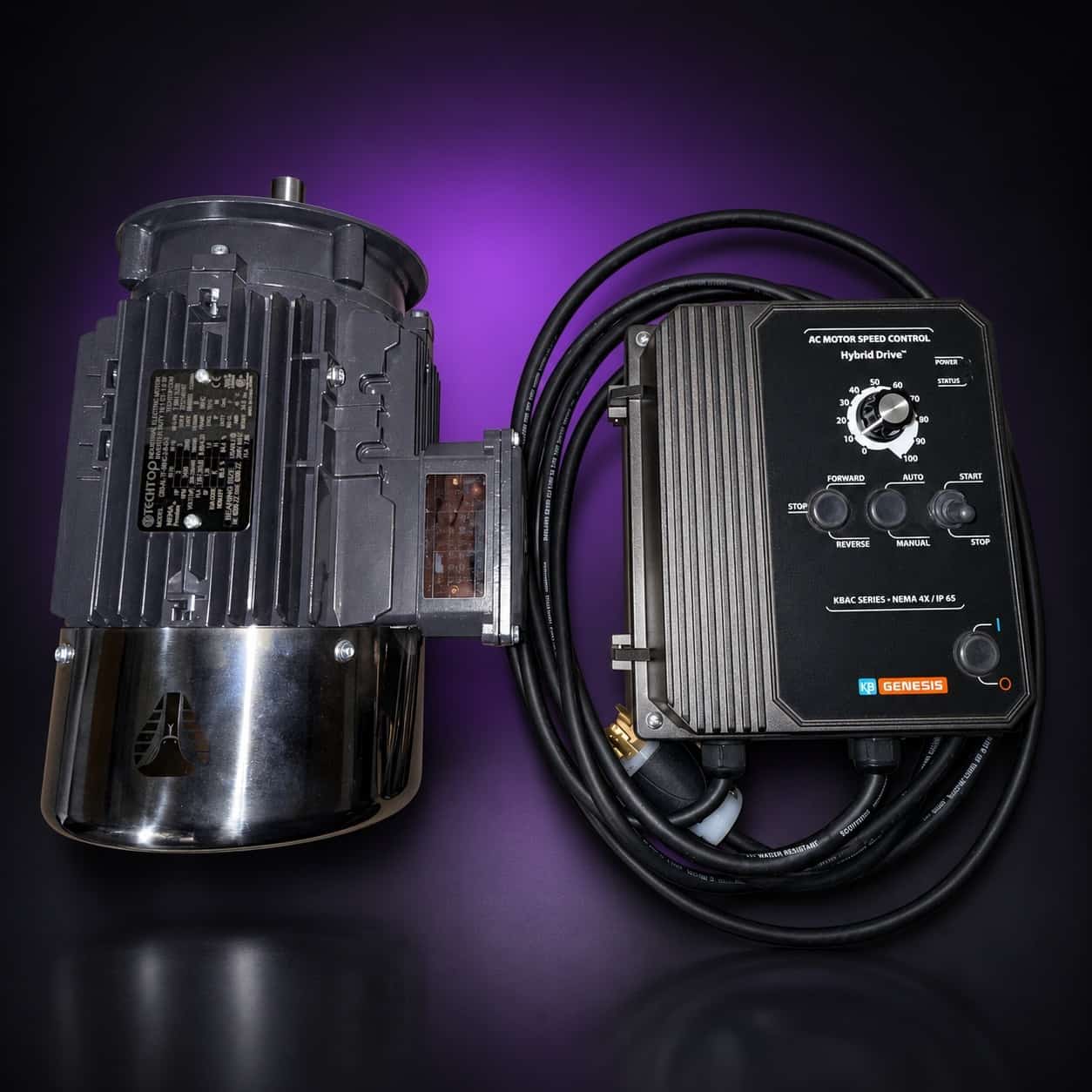
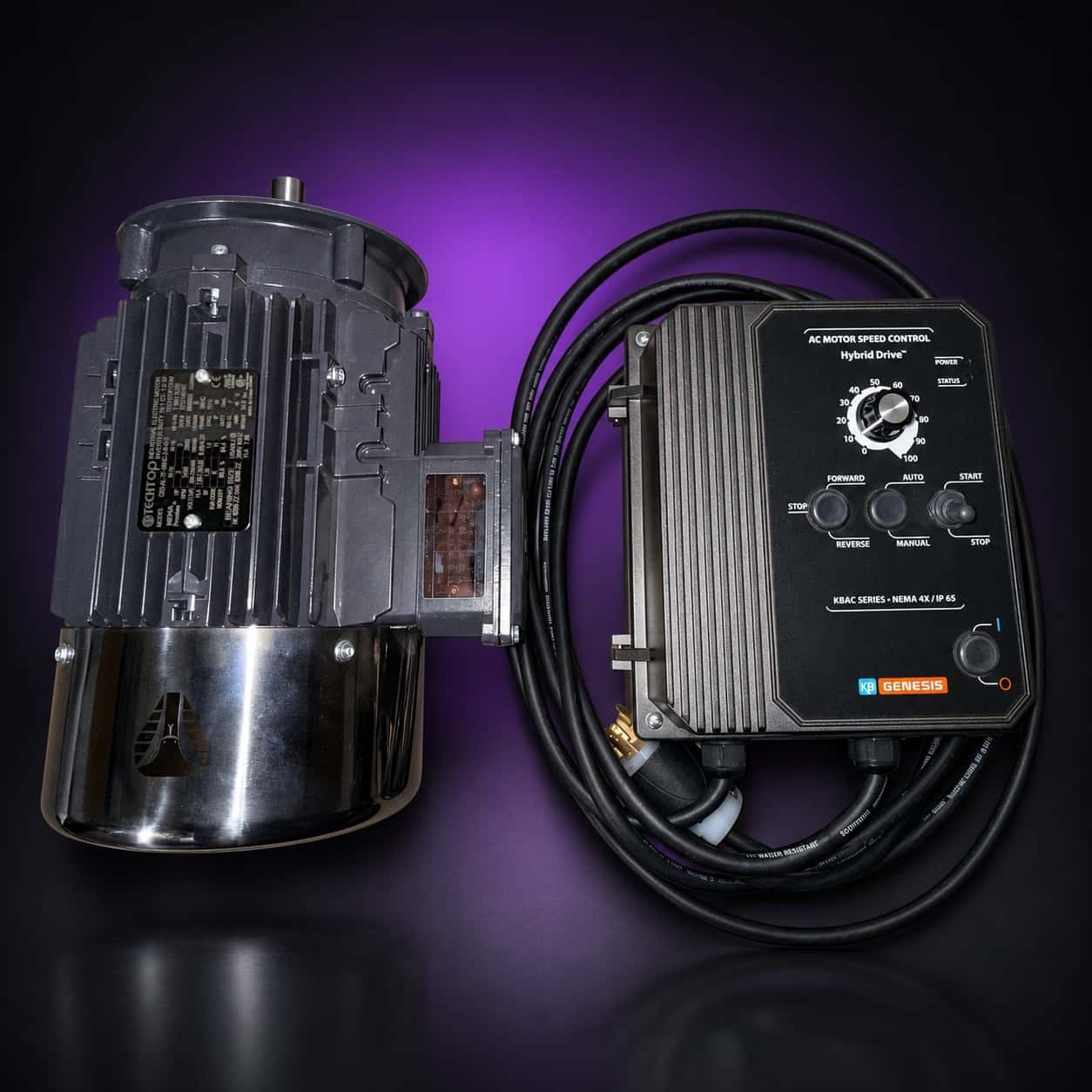
Techtop motor and KB Genesis KBAC variable-speed drive with its power cord, top-down view, on black with a purple glow

Shop guide

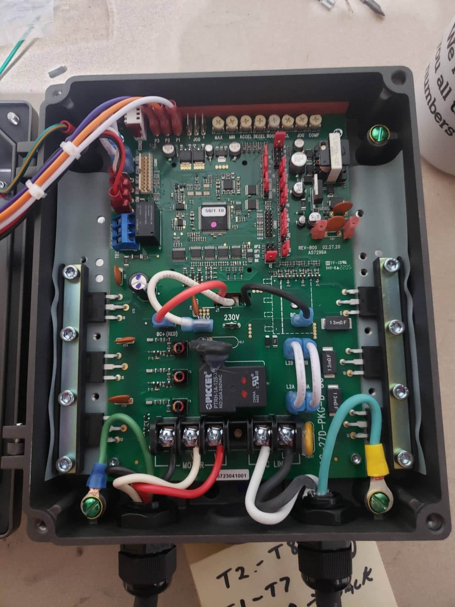
Wiring your VFD, motor, cable and plugs.

A bare 2×72 chassis becomes a grinder when the motor spins. This guide covers the cord and plug wiring you finish after the VFD arrives programmed and mounted.

Before you start

Read this first

A bare 2×72 chassis becomes a grinder the moment the motor spins. This is my step-by-step guide to wiring the VFD, motor, cable and plugs that get you there.

I wire every motor package I sell this way. If you bought my motor and VFD combo, the drive side is already done and programmed; you are wiring the power cord and plug. If you sourced your own parts from the Amazon links page, start at the top and go in order. Read the manuals for your specific VFD and motor first, and when in doubt, ask an electrician.

Step by step

Wiring the drive, the motor and the plug

1. Getting Started

This guide covers the general wiring of a VFD (variable frequency drive), motor, cable and plugs for a stand-alone 2×72 chassis. Model-specific terminal layouts vary, so treat this as the roadmap and your manuals as the map.
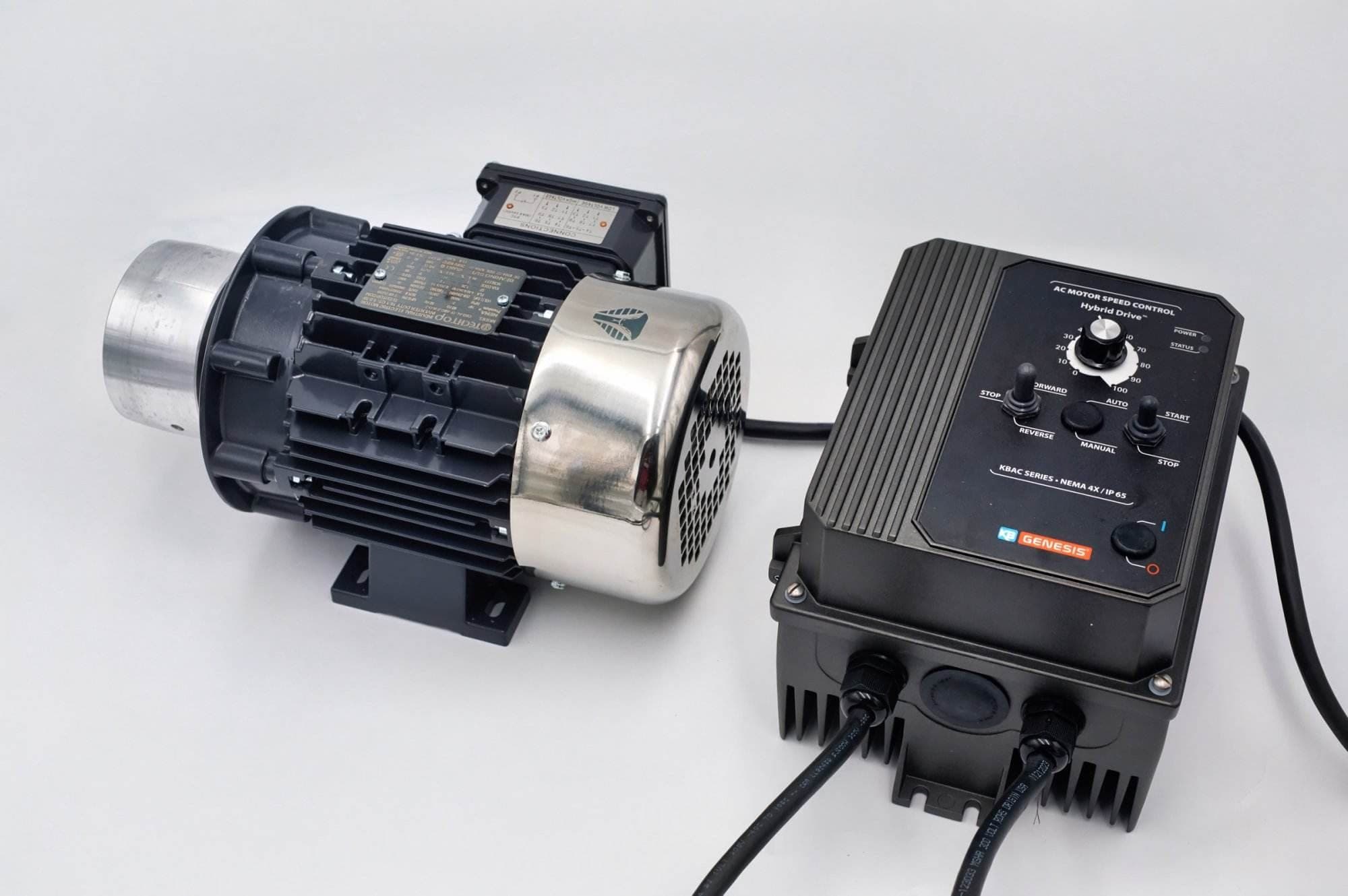
TechTop electric motor paired with a KB Genesis variable speed AC motor control box on a bench

2. Parts & Tools Required

Before you begin, make sure you have all the necessary components and tools:
  • Components:
    • VFD (Variable Frequency Drive)
    • Motor (compatible with your VFD specifications)
    • High-Quality Cable (sized appropriately for your current load)
    • Plugs and Connectors (ensure they meet your wiring needs)
    • 2×72 Stand Alone Chassis Kit:
      • Pre-cut aluminum or steel chassis parts
      • Mounting hardware
      • Wire management accessories (zip ties, cable clamps)
  • Tools:
    • Screwdrivers
    • Wire strippers/cutters
    • Electrical tape or heat shrink tubing
    • Multimeter for testing connections

3. Wiring Instructions

Step 1: Preparing Your Components

  • Read the manuals for your VFD and motor.
  • Inspect all cables and plugs for defects or damage before starting.
  • Plan your layout: Organize your wiring paths to avoid crossing or tangling wires.

Step 2: Wiring the VFD and Motor

  • Connect the power input cables to your VFD as specified by the manufacturer.
  • Wire the motor: Attach the motor cables to the designated output terminals on the VFD.
  • Double-check polarity and secure connections to ensure a safe and reliable setup.

Step 3: Installing the Cable and Plugs

  • Strip the cable ends using a wire stripper.
  • Attach the plugs: Make sure each conductor is properly terminated.
  • Test each connection with a multimeter to verify continuity and proper wiring.
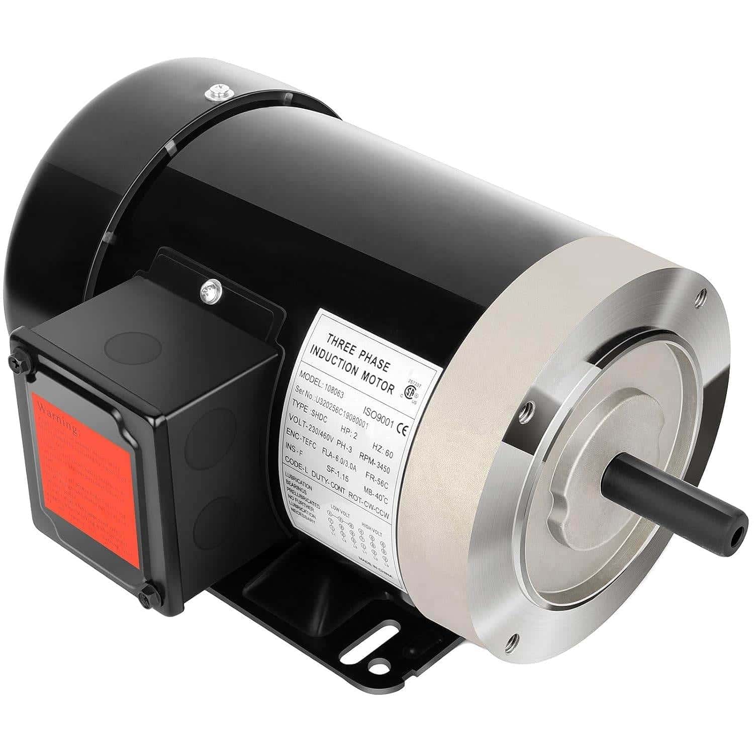
  • Black three-phase 2 HP TEFC electric motor with junction box and mounting base, studio shot
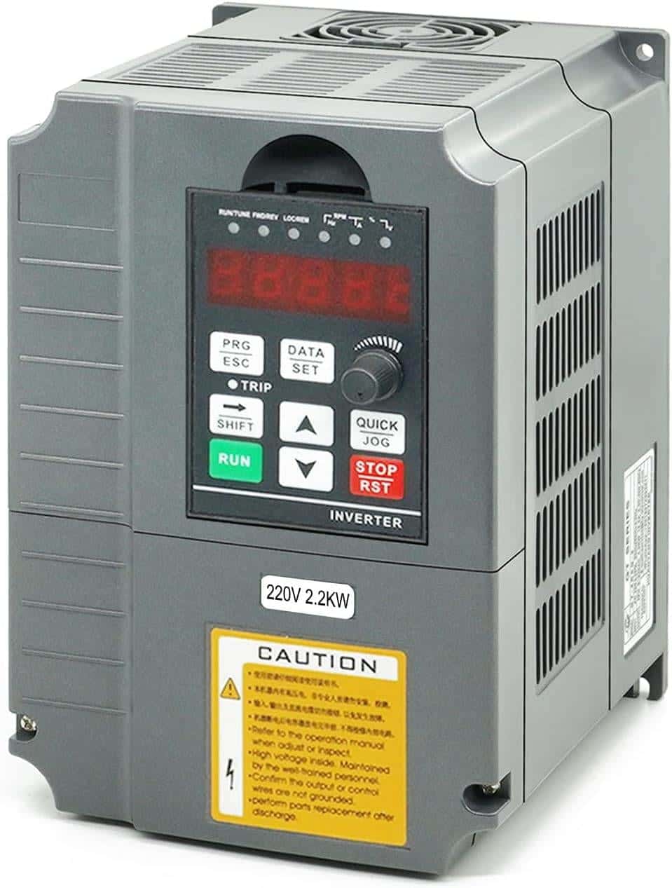
  • Gray variable frequency drive with digital display and caution sticker, rated 220V 2.2kW
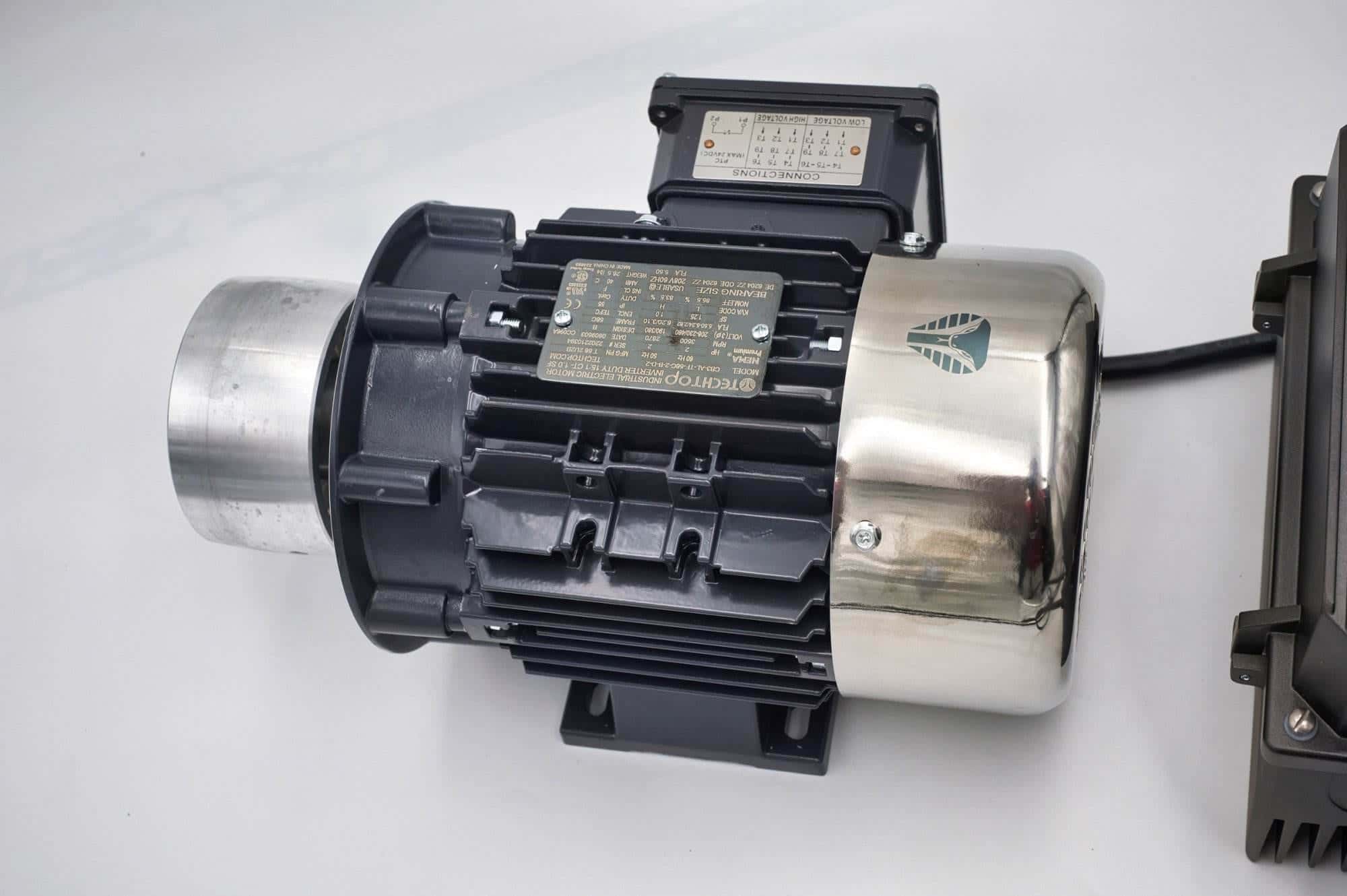
  • Close-up of a TechTop industrial motor's wiring connection box and nameplate on a Torus CNC grinder

4. Assembling the 2×72 Stand Alone Chassis

Chassis Assembly

  • Lay out all chassis components and verify that all parts are present.
  • Securely mount your VFD and motor on the chassis using brackets or mounting plates.
  • Manage your wiring: Use cable clamps and zip ties to neatly secure and route your cables along the chassis.

Final Check

  • Inspect all connections: Confirm that no cables are loose or improperly terminated.
  • Perform a system test before powering up the entire setup.
  • Adhere to safety protocols as recommended by your component manufacturers.
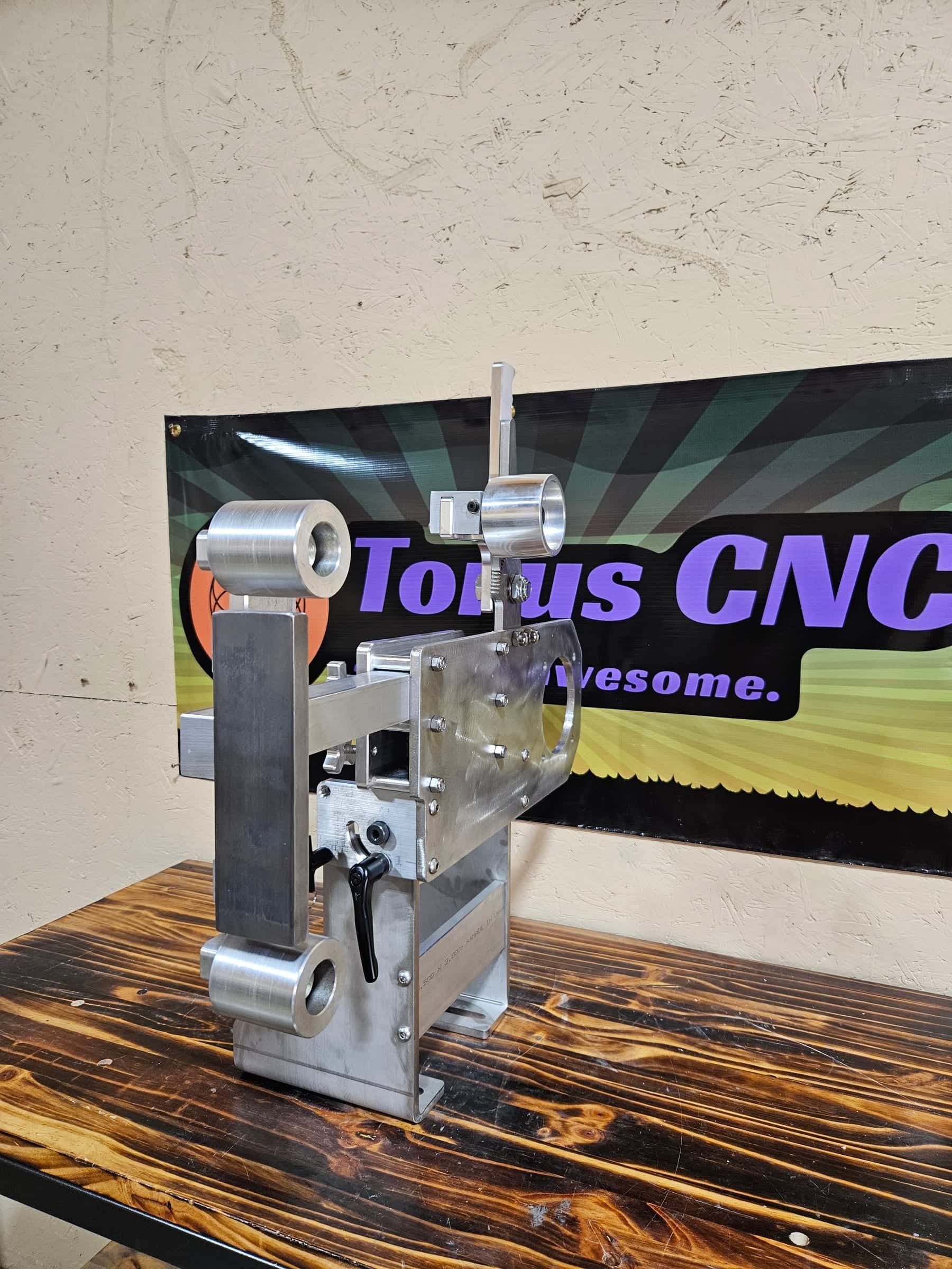
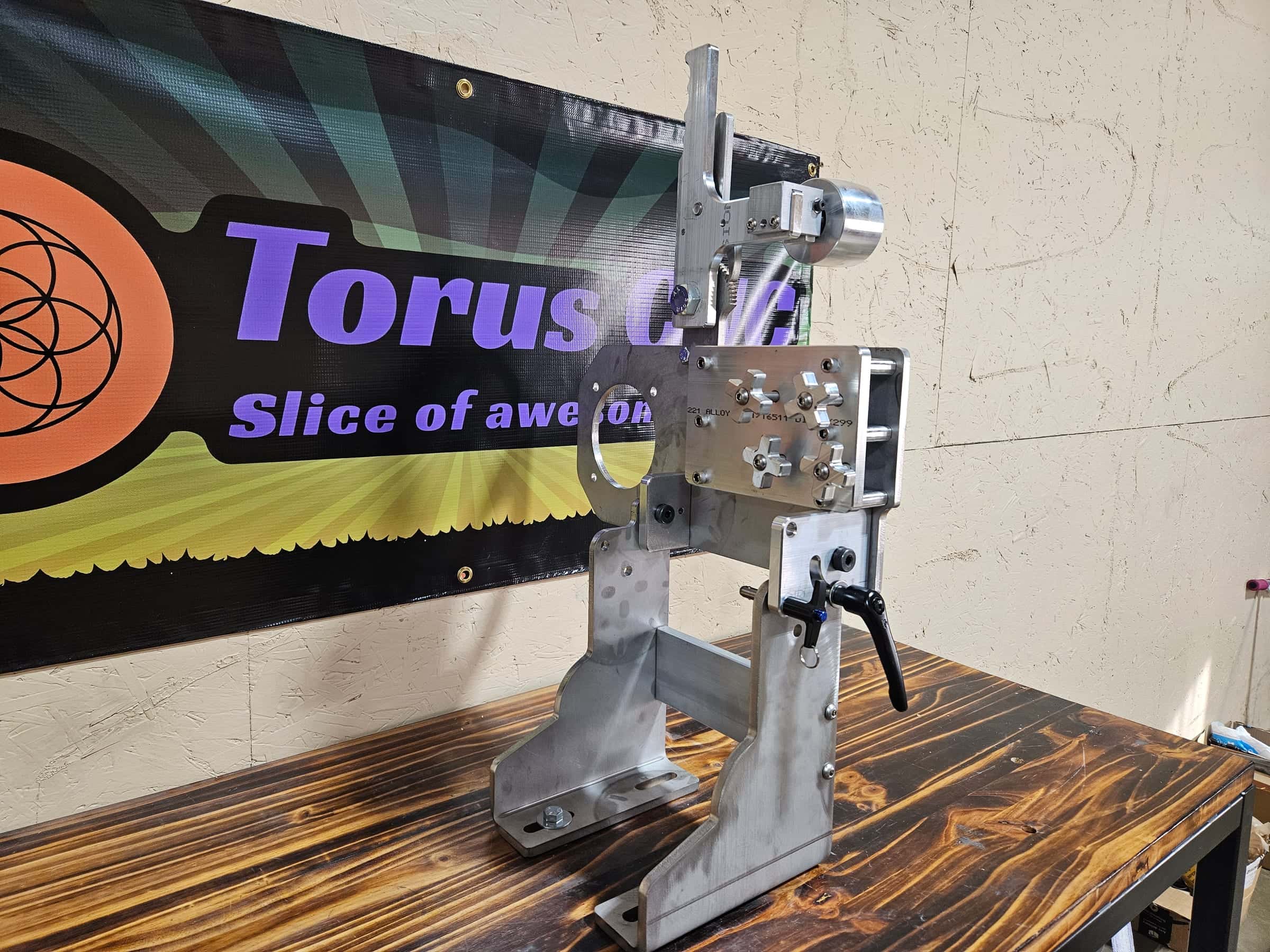
  • Aluminum Torus CNC belt grinder tracking arm with idler wheels standing on a workbench in front of the shop banner
  • Front view of a Torus CNC aluminum belt grinder arm showing knurled adjustment knobs and a 221 alloy stamp
  • Cross-knob tension adjusters and idler wheel mount on a Torus CNC 2x72 grinder tooling arm
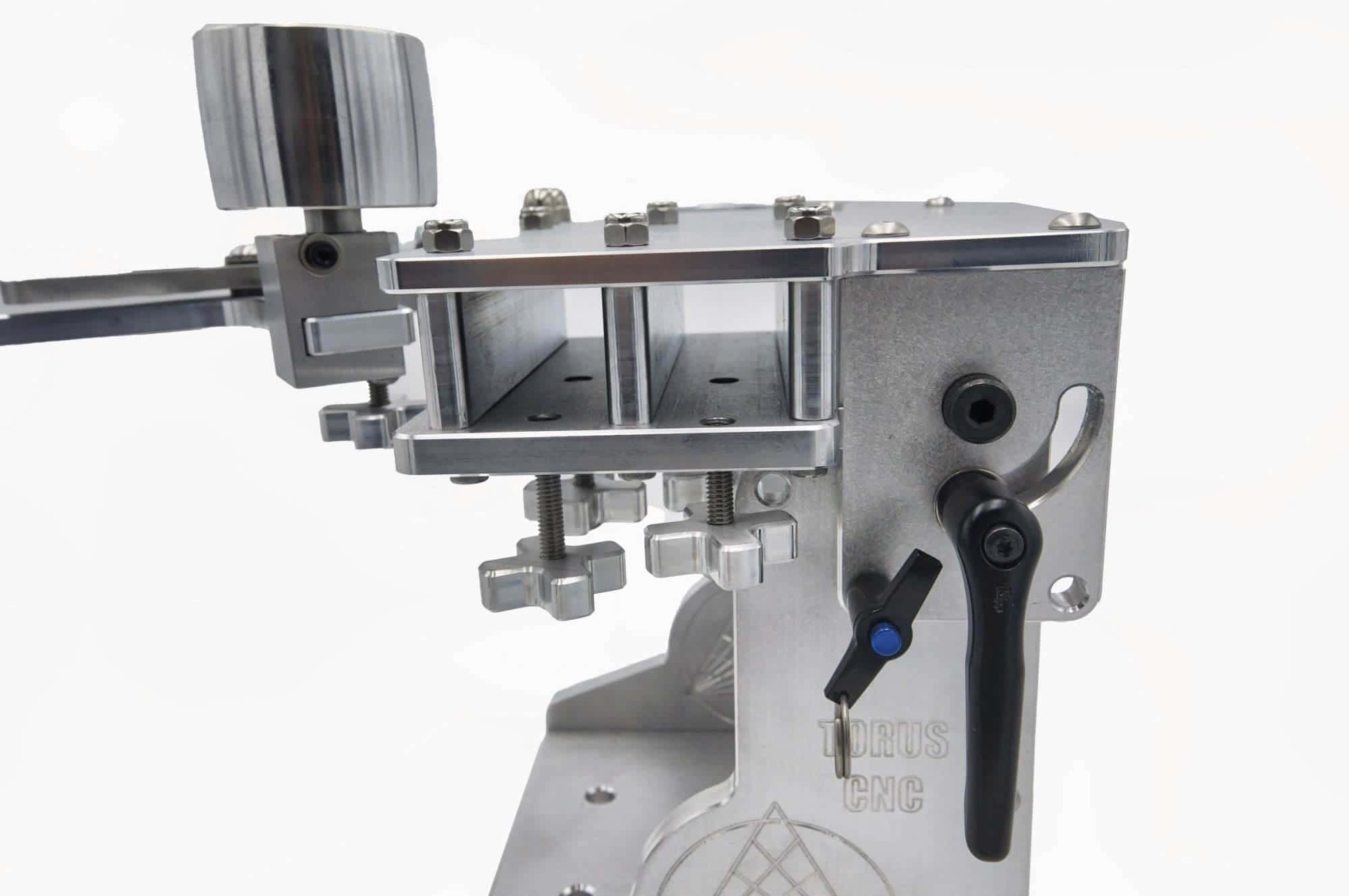
  • Base of a Torus CNC tooling arm frame showing riveted safety warning labels and mounting bolts
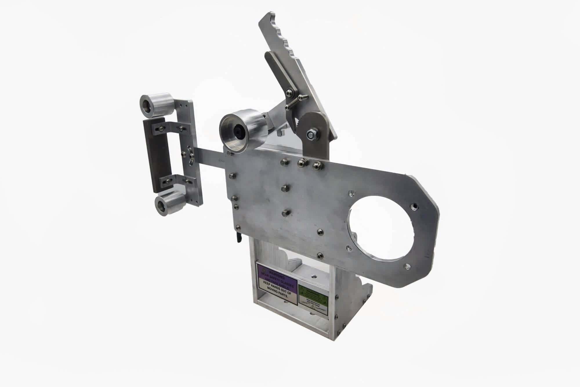
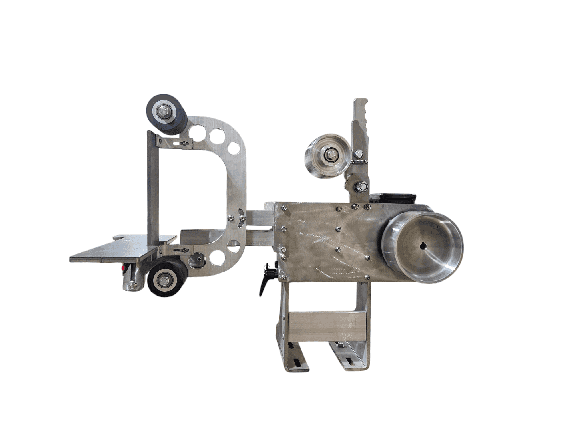
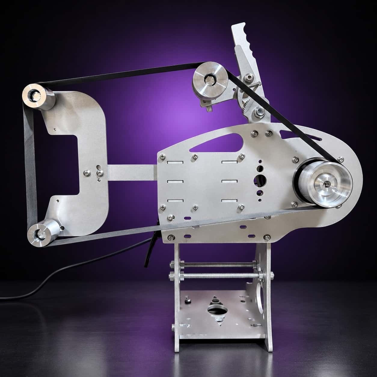
  • Studio product photo of a Torus CNC aluminum 2x72 belt grinder head on a white background, wheels and arm visible

5. Safety Precautions

Safety first, every time.

  • Disconnect power before making any wiring changes.
  • Consult a professional if you are uncertain about any step.
  • Ensure all components are rated for the intended electrical load.

Amazon Affiliate Disclosure

Follow the steps above and you will have a wired, tested motor and drive ready to bolt to a chassis.

Ready to build? The motors, VFDs and cords I recommend are on the Amazon links page, and a Nova 2×72 or Classic chassis is waiting for them.

Disclosure: This page contains affiliate links, including those to Amazon. As an Amazon Associate, we earn from qualifying purchases at no additional cost to you. All opinions expressed here are our own, and our participation in the Amazon Services LLC Associates Program does not affect the price you pay for any products. We only recommend products we truly believe in, and we update our recommendations to reflect the latest information as of April 2025.


Build carefully and wire safely. — Rich

Rather not

Buy the VFD programmed and mounted

The VFD in each motor package arrives programmed and mounted; you finish the cord and plug wiring with the supplied guide.
One-man shop

Stuck halfway through a terminal block?

Send me a photo of your drive and motor plate with the terminal or wiring question you need help with.